Airlifts combine pumping, water treatment in recirculation systems
Pumps use buoyancy of entrained air bubbles to lift water

Intensive tank culture for fish grow-out typically utilizes water recirculation technology with treatment processes for aeration, suspended and dissolved solids, nitrogenous wastes and carbon dioxide removal. Recirculating aquaculture is energy-intensive, because water must move continuously through the system to remove these wastes and replace the oxygen.
The most common method for moving water in recirculating aquaculture systems is the use of a centrifugal pump. Airlift pumps offer an alternative pumping mechanism that uses the buoyancy of the entrained air bubbles to lift the water.
For low-head systems, airlift pumps are more energy-efficient and provide more aeration, carbon dioxide removal and foam fractionation for dissolved solids removal than centrifugal pump systems. Capital and operational costs are lower than standard electrical centrifugal pumps. System design is also simplified.
Experimental airlift system
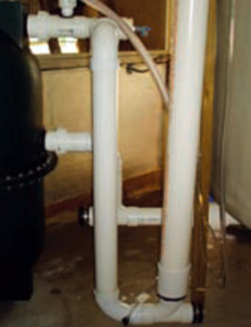
The authors recently designed and tested an experimental airlift unit that included a 7.9-cubic-meter circular fiberglass tank with 1.0 meter of water depth and a 0.14-cubmic-meter Polygeyser biofilter with enhanced media of 55 percent porosity. Water from the tank center drain gravity flowed to the filter through a 7.6-cm-diameter pipe. The airlift riser pipe from the biofilter returning to the tank was 10.2 cm in diameter. Air for water movement was supplied from the facility’s regenerative air blower system.

Sodium sulfite and a cobalt chloride catalyst were used to bring the dissolved oxygen concentrations in the tank below 1 mg per liter. During the re-aeration tests, dissolved oxygen was measured at one- to five-minute intervals until the tank dissolved oxygen was 80 to 90 percent of saturation. Pitot tubes were set up on the airlift riser pipe and from the tank to calculate the static and dynamic head of the airlift system.
Design sequence
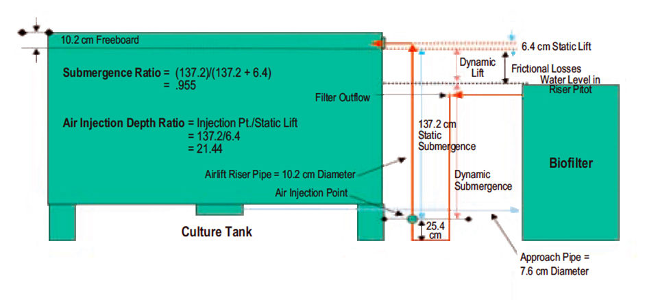
A schematic of the experimental unit is presented in Fig. 1. The basic design sequence in setting up the biofilter for airlift operation on the main tank is outlined below.
- Set the static water lift back into the tank at no more than 30.5 cm.
- Size the diameter of the approach pipe from the center drain to the biofilter so that the projected water flow velocity in the pipe is at least 61.0 cm per second.
- Size the diameter of the lift pipe from the outlet of the biofilter back into the tank to allow a water flow velocity of at least 0.6 meters per second.
- Maintain a submergence:lift ratio of greater than 80 percent. For example, if the water must be airlifted 15.2 cm back into the tank, air injection in the lift pipe is placed 76.2 cm below the lift point.
Results
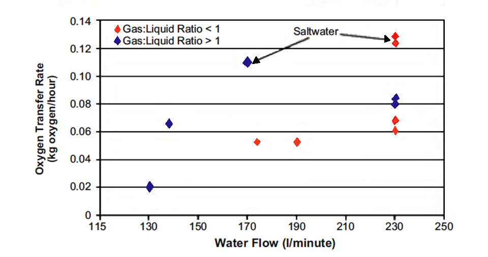
As expected, in operation, the dynamic head increased with increasing water flow (Fig. 2). To maintain two tank water exchanges hourly through the biofilter (approximately 227.0 liters per minute) and minimize dynamic frictional losses to under 30.5 cm, a tank freeboard no greater than 10.2 cm was required.
A greater freeboard in the tank increases the airlift needs, and consequently a greater air flow is required to maintain the recirculating water flow rate. Greater freeboard in the tank decreases the water level in the tank. The lower water level provides less head for the gravity flow of water to the biofilter. Consequently, water flow through the filter is reduced, or additional air must be supplied to maintain set flow rates.
At the desired recirculating flow rate of 227.0 liters per minute, an air:water flow ratio greater than 1 did not result in significantly greater oxygen transfer rates. Standard oxygen transfer rates were greater in trials with 15 to 30 ppt saltwater than in freshwater trials (Fig. 2).
(Editor’s Note: This article was originally published in the March/April 2008 print edition of the Global Aquaculture Advocate.)
Now that you've reached the end of the article ...
… please consider supporting GSA’s mission to advance responsible seafood practices through education, advocacy and third-party assurances. The Advocate aims to document the evolution of responsible seafood practices and share the expansive knowledge of our vast network of contributors.
By becoming a Global Seafood Alliance member, you’re ensuring that all of the pre-competitive work we do through member benefits, resources and events can continue. Individual membership costs just $50 a year.
Not a GSA member? Join us.
Authors
-

USDA Agricultural Research Service
Sustainable Marine Aquaculture Systems
5600 U.S. Highway 1 North
Fort Pierce, Florida 34946 USA -
Louisiana State University
Department of Civil and Environmental Engineering
Baton Rouge, Louisiana, USA
Related Posts
Responsibility
A look at unit processes in RAS systems
The ability to maintain adequate oxygen levels can be a limiting factor in carrying capacities for RAS. The amount of oxygen required is largely dictated by the feed rate and length of time waste solids remain within the systems.
Aquafeeds
A look at the SME controlled extrusion process
A study was conducted using a Twin-Screw Extruder equipped with Specific Mechanical Energy (SME) and Density Control valves, to determine the effect of SME on the water stability of shrimp feeds. Further research is needed to evaluate the performance.
Responsibility
Advances in super-intensive, zero-exchange shrimp raceways
Research at the Texas AgriLife Research Mariculture Laboratory is investigating ways to improve the economic viability of super-intensive raceways for shrimp production.
Health & Welfare
Brazil’s intensive shrimp nursery systems improve PL management, grow-out ponds
Intensive nursery systems are an extension of hatcheries to acclimate postlarvae to farm conditions and assess quality and health prior to pond stocking.