Settling basin design, operation
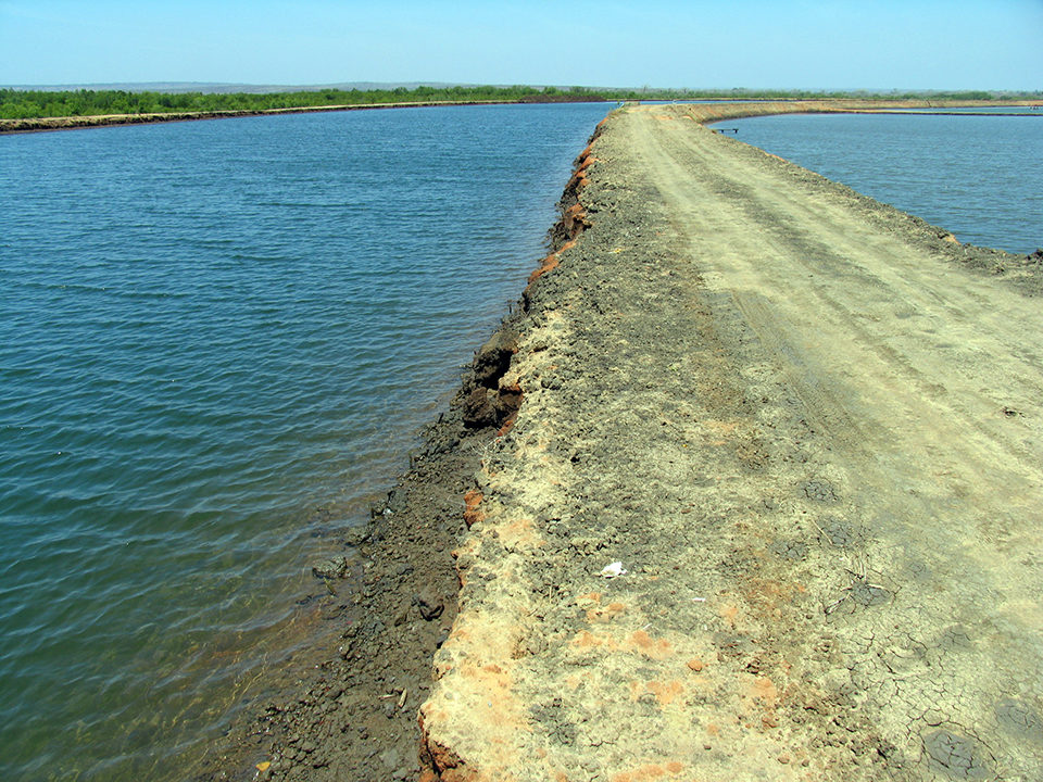
Design and construction should minimize erosion of earthwork
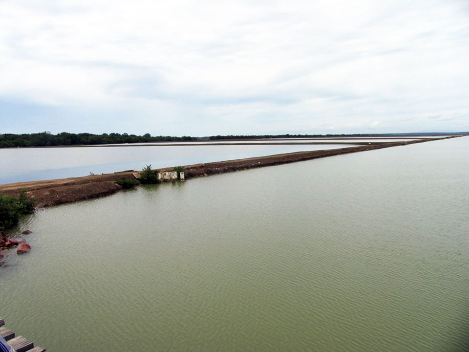
Settling basins are increasingly used in aquaculture to remove coarse, suspended solids from water supplies and draining effluents. They are also effective in retaining sludge dredged or washed from ponds. Some simple guidelines can assist in the design and operation of settling basins.
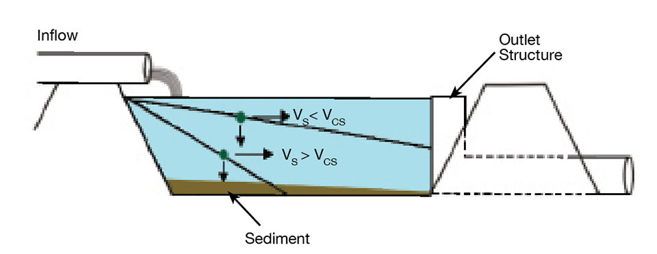
To begin with, the inflow and outflow of a settling basin are roughly equal. The length of time that a water molecule remains in a settling basin – the hydraulic residence time (HRT) – can be estimated by dividing basin volume (V) by inflow rate (Q). Gravity acts on suspended particles, and under quiescent conditions in a settling basin, the fraction of the particles that have a settling time equal to or less than the HRT are retained in the basin (Fig. 1).
Settling velocity
The settling velocity of suspended particles depends mainly upon their densities and diameters. Larger particles settle faster than smaller particles. For example, a fine sand particle will settle over 200 times faster than a medium-sized silt particle. Clay particles settle even slower than silt particles, and many of them usually remain in settling basin discharge.
Mineral soil particles have densities around 2.50 g/cm3, while organic particles have densities of 1.05-1.10 g/cm3. Since organic particles settle much more slowly than mineral particles, settling basins are not effective in removing small organic particles such as plankton and detritus from water.
Mineral particles have terminal settling velocities (VS) in relation to their diameters (Table 1). As indicated in the table, the HRT necessary for removal of particles larger than 0.004 mm is quite long and seldom practical for large inflow rates.
Boyd, Settling velocities and times, Table 1
| Particle Diameter (mm) | Terminal Settling Velocity (m/second) | Time to Settle 1 m (hours) |
|---|---|---|
| 0.060 | 3.3 × 10⁻³ | 0.084 |
| 0.040 | 1.5 × 10⁻³ | 0.185 |
| 0.020 | 3.6 × 10⁻⁴ | 0.770 |
| 0.010 | 9.2 × 10⁻⁵ | 3.020 |
| 0.008 | 5.9 × 10⁻⁵ | 4.710 |
| 0.006 | 3.3 × 10⁻⁵ | 8.400 |
| 0.004 | 1.5 × 10⁻⁵ | 18.500 |
| 0.002 | 3.7 × 10⁻⁶ | 75.000 |
| 0.001 | 9.2 × 10⁻⁷ | 302.000 |
Settling basin design
Typically, the basic information needed for designing a settling basin includes the size distribution of particles in the water to be passed through the basin, the estimated rate of inflow and determination of the smallest particle size to be removed.
Size selection depends upon the volume of effluent and space available for the basin, because the smaller the minimum particle size and the greater the inflow, the larger the basin must be. For aquaculture effluents, it should suffice to select a minimum particle size with the range of 0.006 to 0.020 mm.
The critical settling velocity (Vcs) is the minimum velocity at which a particle can settle and yet be removed (Fig. 1). This velocity can be determined by dividing the mean depth of the settling basin (D) by HRT:

Because HRT = V/Q, the above expression becomes:

Moreover, if we assign a depth of 1 m to the basin, V in cubic meters must equal the basin area (A) in square meters, and the expression for Vcs becomes:

Because we are designing the basin, instead of calculating VCS, we can substitute VS (Table 1) and estimate the area of a 1-m-deep basin for a particular particle size and inflow rate.
Example
Suppose a settling basin is to remove solids greater than 0.008 mm from a maximum inflow of 0.25 m3/second. Particles of the minimum size settle at VS = 5.9 x 10⁻⁵ m/second. The necessary area for a 1-m-deep basin is 4,237 m2:

Of course, the area could be lessened in proportion to greater depth. If the basin was 1.7 m deep, the area would only need to be 2,491 square meters (4,237 m2 ÷ 1.7).
The HRT of a settling basin steadily decreases over time as a result of sediment accumulation. Basins should be constructed with greater than minimum area to avoid having to remove sediment frequently to maintain the minimum HRT.
Other considerations
Settling basins should be designed and constructed to minimize erosion of the earthwork. Inflow should enter at the surface on one side and exit at the surface on the other side. Baffles can be installed in settling ponds to avoid flow passing straight from inlet structure to outlet structure.
Settling basins must not be aerated, for turbulence reduces the settling velocity of particles. If effluent must be aerated before discharge, a separate aeration basin should be installed.
The average depth of settling ponds should be measured at regular intervals to confirm that the minimum design HRT is achieved. When settling basins are cleaned out, sediment should be disposed of in a responsible manner.
Settling basins designed as described above will function primarily to remove coarse mineral solids – suspended soil particles. If space is available to provide an HRT of a day or more, smaller soil particles can settle, and phosphate will be absorbed by sediment in the pond bottom. Some ammonia nitrogen will be nitrified, and some will diffuse into the atmosphere. Denitrification will occur in anaerobic zones of the sediment, and water will be naturally re-aerated. Thus, there are considerable benefits to building settling basins as large as practical.
(Editor’s Note: This article was originally published in the March/April 2012 print edition of the Global Aquaculture Advocate.)
Author
-

Department of Fisheries
and Allied Aquacultures
Auburn University
Auburn, Alabama 36849 USA
Related Posts
Health & Welfare
Common salt a useful tool in aquaculture, part 1
The preventive use of common salt (sodium chloride) by commercial producers of freshwater fishes has many benefits, including helping with the routine prevention of losses due to diseases, stress and mishandling during transport, harvesting, grading, counting, weighing and induced spawning.
Responsibility
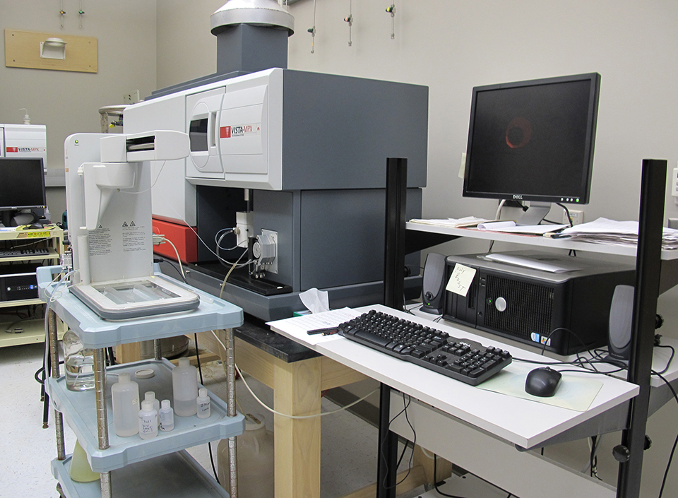
Accuracy of custom water analyses varies
The reliability of trace element analyses reported by custom laboratories cannot be checked by simple techniques, and results may not always be accurate. One should check the reliability of major ion analyses by determining the charge balance and comparing the measured total ion concentration with the total ion concentration estimated from conductivity.
Responsibility
Atmospheric pollution affects water quality
Acid rain typically does not heavily affect aquaculture operations, and application of agricultural limestone can buffer water against the impacts of acid rain at facilities that use stream water.
Responsibility
Calcium and magnesium use in aquaculture
Aquatic plants and animals get the essential nutrients calcium and magnesium from water and food. Calcium concentrations impact the hydration and development of eggs in a hatchery, where calcium carbonate precipitation can be troublesome.