Rectangular airlift pump design outperforms cylindrical units
The surface area:volume ratio can be much lower with a rectangular riser
Rectangular airlift pumps first appeared in the early 1970s. These designs used single horizontal air injectors: either air stones/diffusers or a cylinder with perforations around the perimeter. B. R. Salser and Cornelius Mock presented a rectangular airlift with a diffuser injector for algal culture tanks at the annual meeting of the World Mariculture Society in 1973.
More recently, rectangular airlifts have used injection grids fabricated with fine-pore diffusers or cylinders with multiple perforations. The shortcomings of these grids are air-flow limitations and injector spacing constraints. System air pressure must be increased to deliver high volumes of air flow. Fine-pore diffuser fouling with bacteria, fungi and other microorganisms and/or calcium also limits air flow.
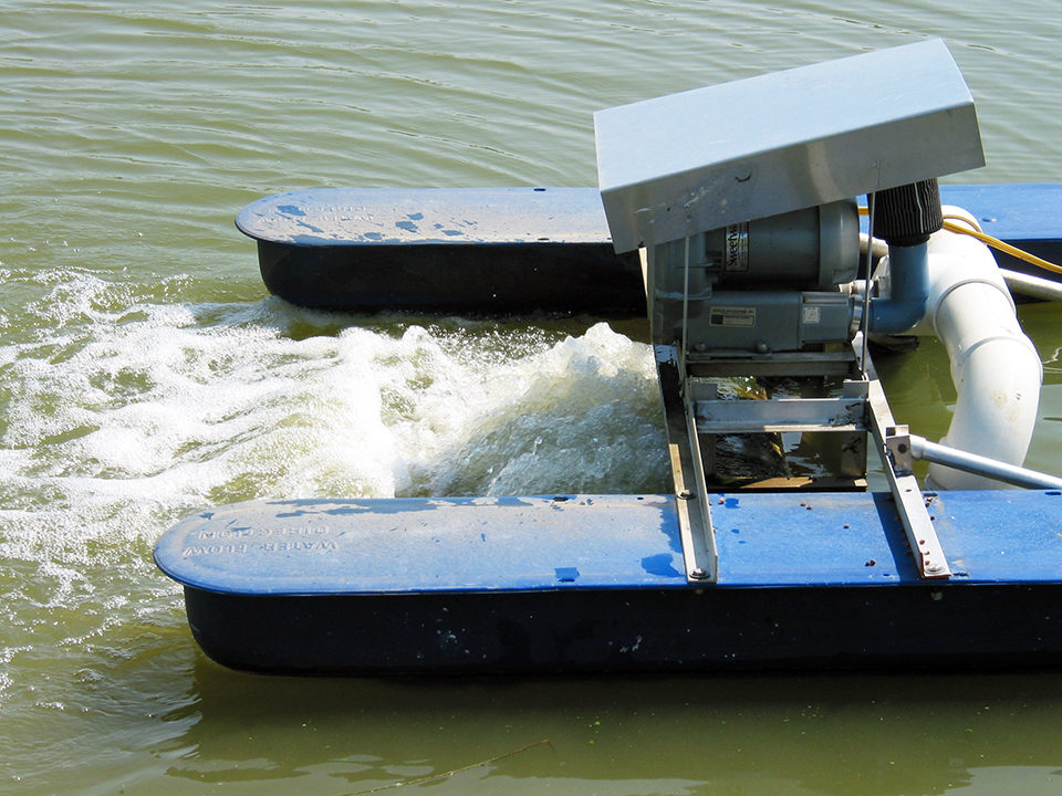
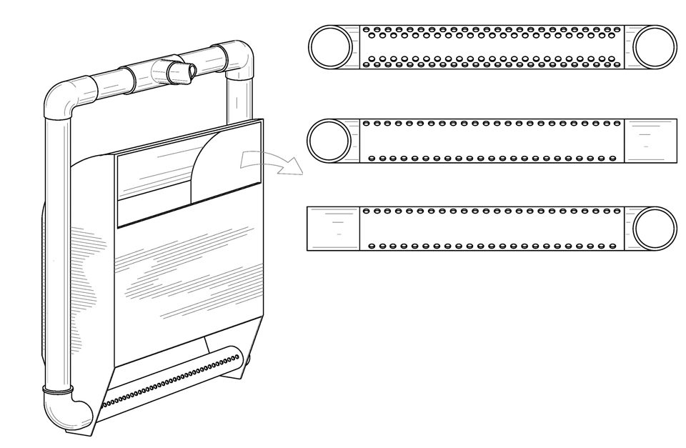
At the 2012 International Conference on Recirculating Aquaculture, the author presented a prototype and designs for compact rectangular airlifts capable of high-volume water output (Figure 1).
Traditional airlift pumps
The traditional airlift pump injects air into a cylindrical chamber/pipe that is partially or fully submerged in a fluid, typically water. The air is injected into the fluid-filled cylinder at the side or in the center of the cylinder, above the intake. The cylinder acts as a mixing chamber for the water and injected air.
In a 1994 World Aquaculture article, the author explained that the air-water mixture is less dense than, and therefore displaced by, the surrounding water. The air-water mixture is forced out of the mixing chamber and through the discharge outlet at the top of the cylinder. A steady flow of injected air produces a constant air-water mixture that is continually pushed to the surface and creates the pumping action of the airlift pump.
Pumping rates in airlift pumps are limited by cylinder diameter and the air injection methods required for cylindrical mixing chambers. To increase flow rates beyond a single cylinder’s capacity, the output of several cylinders must be combined. This requires a cumbersome assembly of multiple airlift cylinders that must be connected with potentially significant space requirements. Each cylinder needs its own independent air injector and, as a result, an extensive air delivery system is necessary.
For any given air flow rate, friction and inline pressure increase as the length of the air distribution pipe (delivery system) increases. Essentially, the efficiency of air delivery to the pumping cylinders drops as the size of the air distribution system is increased to include multiple airlift cylinders. A single, compact and efficient airlift with high-volume output would be desirable.
Rectangular airlifts
The geometry of a rectangular riser has some advantages over cylinders for building airlift pumps. Cylinders and square tubes have the same surface area:volume ratio when the diameter of the cylinder equals the length of the square’s sides. But when a rectangular riser is used, the surface area:volume ratio can be much lower than those of cylinders and square tubes, depending on the dimensions of the rectangle. The larger the dimensions of the rectangular perimeter, the lower the surface area:volume ratio becomes.
For a rectangular riser with perimeter dimensions large enough to tightly encompass 40 cylinders, the surface area:volume ratio would be five times less than that for the 40 cylinders combined (Table 1). Furthermore, if made of the same material, 40 cylinders would be over four times heavier than the rectangular riser. Surface area is important with respect to fluid flow and resistance. As surface area increases, resistance to fluid flow increases. A lower surface area:volume ratio means less fluid resistance, and higher flow rates are possible.
Wurts, Surface area:volume, Table 1
| Riser | Dimensions (cm) | Area/Volume (cm2/cm3) |
|---|---|---|
| Cylinder | 7.5 x 30.0 | 0.530 |
| Square tube | 7.5 x 7.5 x 30.0 | 0.530 |
| Rectangular | 30.0 x 30.0 x 75.0 | 0.093 |
Typical design limitations
Several recent rectangular airlifts use grid systems to inject air into the riser. These grids are typically constructed with multiple diffuser hoses or perforated cylinders placed parallel to one another. The injector cylinders or diffuser hoses are often relatively small in diameter. These multiple parallel elements are connected to one another and the air-distribution manifold with several 90 degrees fittings.
The 90 degrees bends in the distribution system, as well as small-diameter distribution lines and injector cylinders/hoses, can produce considerable turbulence and resistance. These can cause substantial air flow loss, limiting water output volume. Furthermore, the dimensions of the fittings used to connect the injector cylinders with one another determine the minimum distance between cylinders, restricting spacing options.
Although fairly common, the single row of small holes down the top center of each injector cylinder is unlikely to effectively handle the total air volume delivered to the grid, resulting in more air flow loss. Multiple perforations around the entire circumference of an injector cylinder create uneven pressure within the cylinder – more at the bottom and less at the top.
The fine pores of diffuser hose injectors can create high resistance to air flow, which in turn reduces air flow and pumping outputs. Small holes in cylinders or the fine pores of diffusers are susceptible to biofouling and calcification, both of which can block air flow entirely.
High-volume prototype
In late 2006 and early 2007, the author designed and R. G. Herron built a prototype rectangular airlift pump. The designs were submitted to the United States Patent and Trademark Office as a provisional patent in 2008 and as a non-provisional patent application with new design elements and improvements in 2009. The author presented these designs in 2012 at the International Recirculating Aquaculture Conference in Roanoke, Virginia, USA.
The designs employed either single- or dual-cylinder, horizontal air injector elements. Air was injected through portals (circular apertures) in the cylinder walls. Unlike earlier documented designs, the air-injector portals were placed in bilateral single or double rows, just above the midlines of the injector cylinder. The perimeters of the lowest air portals were tangential to the top of the injector cylinder’s midlines.
The bilateral configuration of air portals provided symmetrical airstream distribution, more precise injection depths and air-stream exposures to equal volumes of water – both sides of the air streams. The diameters of the air injector cylinders and portals were designed to handle high air flow rates and minimize the potential for fouling.
Perspectives
Rectangular airlifts can be compact and more space efficient than airlifts made with combinations of multiple cylinders. They can generate much higher water volume outputs than single-cylinder airlifts. If properly designed, a single compact rectangular airlift can handle the total air output of one or two regenerative/centrifugal blowers.
Rectangular airlift pumps can generate high-volume water flow rates at relatively low static air pressures. Airpump software developed by Douglas Reinemann and Michael Timmons at Cornell University in 1988 indicates a single rectangular airlift at 100 percent submergence should pump water volumes of 9,538-11,960 Lpm/kw, with an air flow of 2,284 Lpm/kw and riser volume of 0.18-0.21 m3. Potential applications include circulation, pumping and aeration in recirculating systems or ponds.
(Editor’s Note: This article was originally published in the November/December 2012 print edition of the Global Aquaculture Advocate.)
Author
-

Extension Aquaculture Specialist
Kentucky State University CEP
P. O. Box 469, UKREC
1205 Hopkinsville Street
Princeton, Kentucky 42445 USA
Related Posts
Health & Welfare
Building a better shrimp nursery, part 2
Shrimp nursery systems offer the shrimp industry an important opportunity to increase profits, by helping produce strong, healthy and uniform juveniles with significant potential for compensatory growth after their transfer for final pond grow-out. Biofloc technology and water quality are critical components of shrimp nursery systems.
Health & Welfare
Crowder/grader units improve harvest efficiency in large circular tanks
The use of larger and deeper tanks can reduce building, labor and other aquaculture production costs. However, the ability to grade and transfer large numbers of fish is more challenging when using large tanks. In a comparison of the effectiveness of a purse seine and a hinged clamshell to crowd fish in large tanks, the latter was easier to control and less stressful to salmonids. With a slotted bar rack in a side panel of the clamshell crowder, fish were simultaneously graded in size.
Responsibility
Emerging trends in salmonid RAS, part 2
Dozens of land-based, closed-containment salmonid RAS systems are coming on line. New projects are bringing new principles into the salmon industry. Industry expansion hinges upon the development of pollution-mitigating technologies to reduce nutrients in effluents.
Health & Welfare
Novel air-based system transfers large salmon during harvest
To evaluate the application of an air pressure-based transport method within a recirculating aquaculture system, the authors performed testing with harvest-size salmon at The Conservation Fund Freshwater Institute.